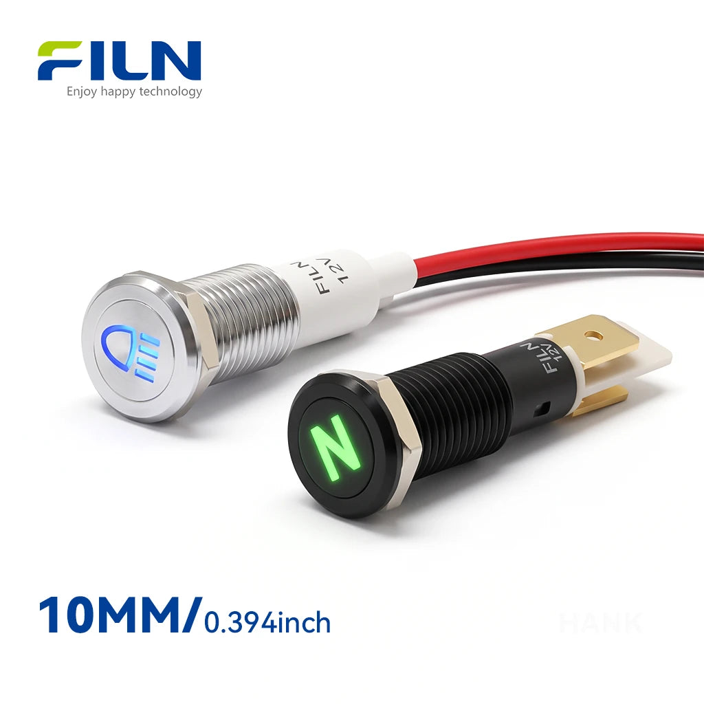


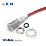


Product Summary
The FILN metal indicator light is a robust industrial-grade status pilot lamp designed for electrical panels, machinery, automation equipment, and commercial installations. Engineered for OEM buyers, control panel builders, and industrial equipment manufacturers, it solves critical reliability issues associated with fragile plastic indicators in high-vibration and harsh environments. Key specifications include mounting hole sizes ranging from 6mm to 30mm, support for 3V to 480V AC/DC operational voltages, high-brightness LED luminescent sources, and an IP65/IP67 waterproof rating. Available configurations feature pin terminals or integrated lead wires, flat, prominent, or concave head types, and brass, stainless steel, or zinc-aluminum alloy shells. Buyers should confirm exact voltage, mounting dimensions, wiring requirements, and environmental protection needs before bulk ordering. FILN provides comprehensive OEM, ODM, custom manufacturing, and wholesale support directly from its 10,000 m² factory.
Indicator Light Symbols & Meanings Reference
The following reference uses the same FILN symbol codes as the 8mm symbol indicator light series. Each code identifies a laser-etched graphic, while the explanation describes its common function in automotive dashboards and industrial control panels. Actual warning behavior can vary by vehicle manufacturer and control-system design.

| Code | Symbol Name | What This Symbol Means | Code | Symbol Name | What This Symbol Means |
|---|---|---|---|---|---|
| 1 | Front Fog Lights | Indicates that the front fog lamps are switched on, typically for use in fog, rain, snow, or other low-visibility conditions. | 2 | High Beam Headlights | Indicates that the vehicle high beam headlights are switched on. |
| 3 | Engine Start / Power Indicator | Indicates engine start, ignition, or vehicle power system status, depending on the vehicle or control system. | 4 | Fire Extinguisher / Fire Warning | Represents a fire warning or fire protection system and may be used to identify fire-extinguishing equipment. |
| 5 | Engine Check / Fault Warning | Indicates that the engine, emissions, or related electronic control system requires inspection. | 6 | Side Marker / Low Beam Lights | Indicates that side marker, position, or low beam lighting is active. |
| 7 | Seat Belt Unfastened | Warns that a driver or passenger seat belt is not fastened correctly. | 8 | Parking Brake (Handbrake) | Indicates that the parking brake is engaged or identifies the parking brake system. |
| 9 | Brake System / Low Brake Fluid | Warns of a brake system condition, such as low brake fluid or another brake-related fault. | 10 | Hazard Warning Lights | Indicates that the vehicle hazard warning flashers or emergency warning lights are active. |
| 11 | Right Turn Signal | Indicates that the right turn signal is active. | 12 | Coolant Overheating Warning | Warns that engine coolant temperature is too high and the engine may be overheating. |
| 13 | Low Fuel Level | Indicates that the fuel level is low and refueling may be required. | 14 | Dual Turn Signals | Represents simultaneous left and right turn signals, commonly associated with hazard warning operation. |
| 15 | Low Engine Oil Pressure | Warns that engine oil pressure is below the expected operating level and requires attention. | 16 | Battery / Charging System Fault | Indicates a possible battery, alternator, or vehicle charging system problem. |
| 17 | Horn Indicator | Represents the vehicle horn or horn control function. | 18 | Engine Start | Indicates an engine start function or engine starting status. |
| 19 | Rear Fog Light | Indicates that the rear fog light is switched on for low-visibility conditions. | 20 | Right Turn Signal | Shows that the right directional turn signal is active. |
| 21 | Side Marker Lights (Position Lights) | Indicates that side marker or vehicle position lights are active. | 22 | Check Engine Light / Exhaust Fault | Indicates a detected engine, emissions, or exhaust-system fault requiring inspection. |
| 23 | General Hazard / Warning Triangle | Provides a general warning or caution indication and may require checking additional vehicle information. | 24 | Smart Key Indicator | Indicates the status of the smart key or keyless entry and start system. |
| 25 | ABS Fault | Indicates a possible fault in the Anti-lock Braking System (ABS). | 26 | Exterior Light Failure Warning | Warns that one or more exterior vehicle lights may have failed or require inspection. |
| 27 | Park Gear (P) | Indicates that an automatic transmission is in Park position. | 28 | Neutral Gear (N) | Indicates that the transmission is in Neutral. |
| 29 | Drive Gear (D) | Indicates that the automatic transmission is in Drive. | 30 | Reverse Gear (R) | Indicates that the transmission is in Reverse. |
| 31 | Brake Pad Wear Warning | Warns that brake pads may be worn and should be inspected or replaced. | 32 | Four-Wheel Drive / Differential Lock | Indicates four-wheel-drive operation or differential-lock engagement. |
| 33 | Automatic Transmission Fault | Indicates a fault or abnormal condition in the automatic transmission or its control system. | 34 | Nitrous Oxide System Active | Indicates that a nitrous oxide performance system is active; commonly associated with specialized or modified vehicles. |
| 35 | Purge System Indicator | Represents a purge or emissions-control system function, depending on vehicle or equipment design. | 36 | Critical Danger Warning | Represents a critical danger or emergency warning condition requiring immediate attention. |
| 37 | Low Beam Headlights | Indicates that the low beam headlights are switched on. | 39 | Engine Control Unit Fault | Indicates a possible fault in the engine control unit or related electronic engine-control system. |
| 40 | Blower Fan Active | Indicates that the HVAC or ventilation blower fan is operating. | 41 | Frost / Icy Road Warning | Warns of low-temperature conditions where frost or icy road surfaces may be present. |
| 42 | Diesel Glow Plug / Pre-Heating | Indicates that the diesel engine glow plugs are pre-heating before engine start. | 43 | Windshield Defrost / Defog | Indicates that the front windshield defrost or defog function is active. |
| 44 | Rear Window Defrost / Defog | Indicates that the rear window heating, defrost, or defogging function is active. | 45 | ESP / Traction Control | Indicates electronic stability control or traction control operation or a related system condition. |
| 60 | Airbag System Fault (SRS) | Indicates a possible fault in the Supplemental Restraint System, including airbags or related components. | 61 | Door Ajar Warning | Indicates that one or more vehicle doors are not completely closed. |
| 63 | Overdrive Off (O/D OFF) | Indicates that the automatic transmission overdrive function has been switched off. | 82 | Washer Fluid Low | Indicates that the windshield washer fluid level is low and may need refilling. |
| 90 | TPMS | Indicates low tire pressure or a possible Tire Pressure Monitoring System condition. | 98 | Auto Hold / Brake System Fault | Represents the Auto Hold function or a related brake-system condition, depending on vehicle configuration. |
| 169 | Convertible Top Unlocked / Open | Indicates that a convertible roof is open, unlocked, or not fully secured. | 170 | Trunk / Tailgate Open | Indicates that the trunk, rear hatch, or tailgate is open or not completely closed. |
| 188 | Parking Sensors / Park Assist | Indicates parking sensors or a parking-assistance system is active or available. | 189 | Headlight Washer System | Indicates the headlight cleaning or washer system. |
| 190 | Fuel Cap Open Warning | Indicates that the fuel filler cap or fuel door may not be properly closed. | 207 | Lighting System Malfunction | Indicates a possible malfunction in the vehicle lighting system. |
| 209 | DPF Warning | Indicates a condition involving the Diesel Particulate Filter, such as soot accumulation or the need for regeneration. | 214 | ECO Driving Mode | Indicates that an economy-focused driving mode is active. |
| 216 | DPF Regeneration / Filter Status | Indicates Diesel Particulate Filter regeneration or filter operating status. | 217 | Wiper Fault | Indicates a possible fault in the windshield wiper system. |
| 218 | Convertible Roof Operation Warning | Indicates that the convertible roof is operating or that a roof operation condition requires attention. | 219 | Tow Hitch / Trailer Lock | Represents trailer coupling, tow hitch, or trailer locking status. |
| 220 | Headlight Range Control | Represents headlight beam-height or illumination-range adjustment. | 230 | Adaptive Headlight Range / Angle | Indicates adaptive headlight range or beam-angle control. |
| 221 | Adaptive High Beam / Light Angle | Indicates adaptive high-beam operation or automatic headlight direction control. | 222 | Distance Warning / Forward Collision | Warns of insufficient distance from a vehicle or obstacle ahead or indicates a forward-collision warning function. |
| 224 | Cruise Control Active | Indicates that the cruise control system is active. | 225 | Hill Descent Control (HDC) | Indicates Hill Descent Control, which assists with controlled vehicle speed on steep downhill roads. |
| 226 | Key Battery Low Warning | Warns that the battery in the smart key or remote key is running low. | 227 | Press Brake Pedal Indicator | Instructs the driver to press the brake pedal before starting, shifting, or performing a related operation. |
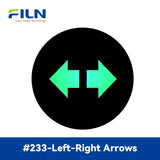
| 228 | Speed Limiter Indicator | Indicates that a vehicle speed-limiting function is active. | 233 | Directional Turn Signals | Represents directional turn signals used to indicate left or right vehicle movement. |
| 234 | Service / Maintenance Required | Indicates that vehicle maintenance, inspection, or service may be required. | 243 | EPS Fault | Indicates a possible fault in the Electric Power Steering system. |
| 244 | Brake System Service Check | Indicates that the brake system should be inspected or serviced. | 245 | Information Indicator | Provides general vehicle information or prompts the driver to check additional information on the display. |
| 246 | Light Sensor / Lane Detection | Represents light-sensing or lane-detection functionality in an automotive control system. | 247 | Key Not Detected / Invalid Key | Indicates that the vehicle cannot detect a valid smart key. |
| 248 | Remote Key Signal / Sensor Warning | Indicates a condition involving the remote key signal or related sensor system. | 249 | Steering Column Lock Warning | Indicates a condition involving the electronic steering column lock system. |
| 251 | Door / Roof Warning | Indicates that a door, roof, or related body opening may not be completely closed or secured. | 252 | Lane Departure Warning (LDW) | Indicates a lane-departure warning function that alerts the driver when unintended lane departure is detected. |
| 253 | Hood Open Warning | Indicates that the vehicle hood is open or not completely closed. | 254 | Adaptive Front-Lighting System (AFS) | Indicates an adaptive front-lighting system that adjusts headlight illumination according to driving conditions. |
| 255 | Side Airbag / Occupant Sensor Fault | Indicates a possible fault involving side airbags or occupant detection sensors. | 256 | Side Slip / Lane Keep Assist | Represents vehicle side-slip control or a lane-keeping assistance function. |
| 257 | Water in Fuel Filter Warning | Commonly used on diesel vehicles to indicate that water has been detected in the fuel filter. | 258 | Suspension System / Shock Absorber Fault | Indicates a possible fault in the suspension or shock absorber system. |
| 259 | Auto Rain-Sensing Wipers | Indicates an automatic rain-sensing windshield wiper function. | 260 | Key Not Found / Engine Immobilizer | Indicates that a valid key is not detected or that the engine immobilizer system is active or reporting a related condition. |
| Custom Symbol Support: FILN supports customized laser-etched symbols for metal indicator lights, automotive dashboard indicators, industrial control panels, machinery, marine equipment, electrical control systems, and OEM applications. Custom symbols can be produced according to customer drawings, samples, or application requirements. | |||||
Note: The symbol names and explanations above describe common automotive and industrial applications. Actual symbol functions, warning conditions, and colors may vary by vehicle manufacturer, equipment manufacturer, model, and control-system design. Always refer to the applicable vehicle or equipment owner's manual for the final interpretation.
Key Takeaways
- The FILN metal indicator light functions as a reliable visual status pilot lamp for industrial control panels, automation systems, and heavy-duty equipment.
- Mounting hole diameters range from 6mm to 30mm, accommodating diverse panel cutouts across global industrial manufacturing sectors.
- Available shell materials include copper alloy, black-plated zinc-aluminum alloy, and stainless steel, providing robust mechanical protection.
- Standard operating voltage spans from 3V to 480V DC/AC, supporting low-voltage electronics and high-voltage power distribution.
- An IP65/IP67 ingress protection rating makes the indicator suitable for dusty environments and temporary water exposure, subject to proper installation sealing.
- Wiring options include pin terminals and integrated wire leads, allowing for flexible electrical assembly methods.
- Head styles are available in flat, prominent (convex), and recessed configurations to match specific aesthetic and functional panel design requirements.
- High-brightness LED luminescent sources deliver an operational life of 50,000 to 100,000 hours under rated electrical conditions.
- FILN supports comprehensive OEM, ODM, and bulk customization services, including custom wire lengths, voltages, and laser-etched symbols.
- Certified under strict quality standards, FILN products serve demanding markets across North America, Europe, and Asia-Pacific.
What is a Metal Indicator Light?
A metal indicator light is an electromechanical status display device utilized in industrial machinery, electrical control cabinets, and commercial appliances to communicate operational modes, power states, and fault conditions. Its primary function is providing clear, immediate visual feedback to equipment operators through high-intensity LED illumination housed within a durable metal enclosure. Structurally, the device consists of a threaded metal shell, a specialized PA66 lamp holder, an internal current-limiting resistor, a high-brightness LED source, a polycarbonate lens, and a silicone sealing O-ring that secures the assembly against panel cutouts via a fastening nut.
Industrial value lies in its superior mechanical resilience compared to standard plastic alternatives, resisting physical impacts, chemical washdowns, and continuous operational vibration. The operating principle relies on applying a rated AC or DC voltage across the internal resistor and LED diode circuit, exciting semiconductor materials to emit specific wavelengths of light. Typical applications span CNC machine tools, electrical power distribution cabinets, EV charging stations, and marine control consoles.
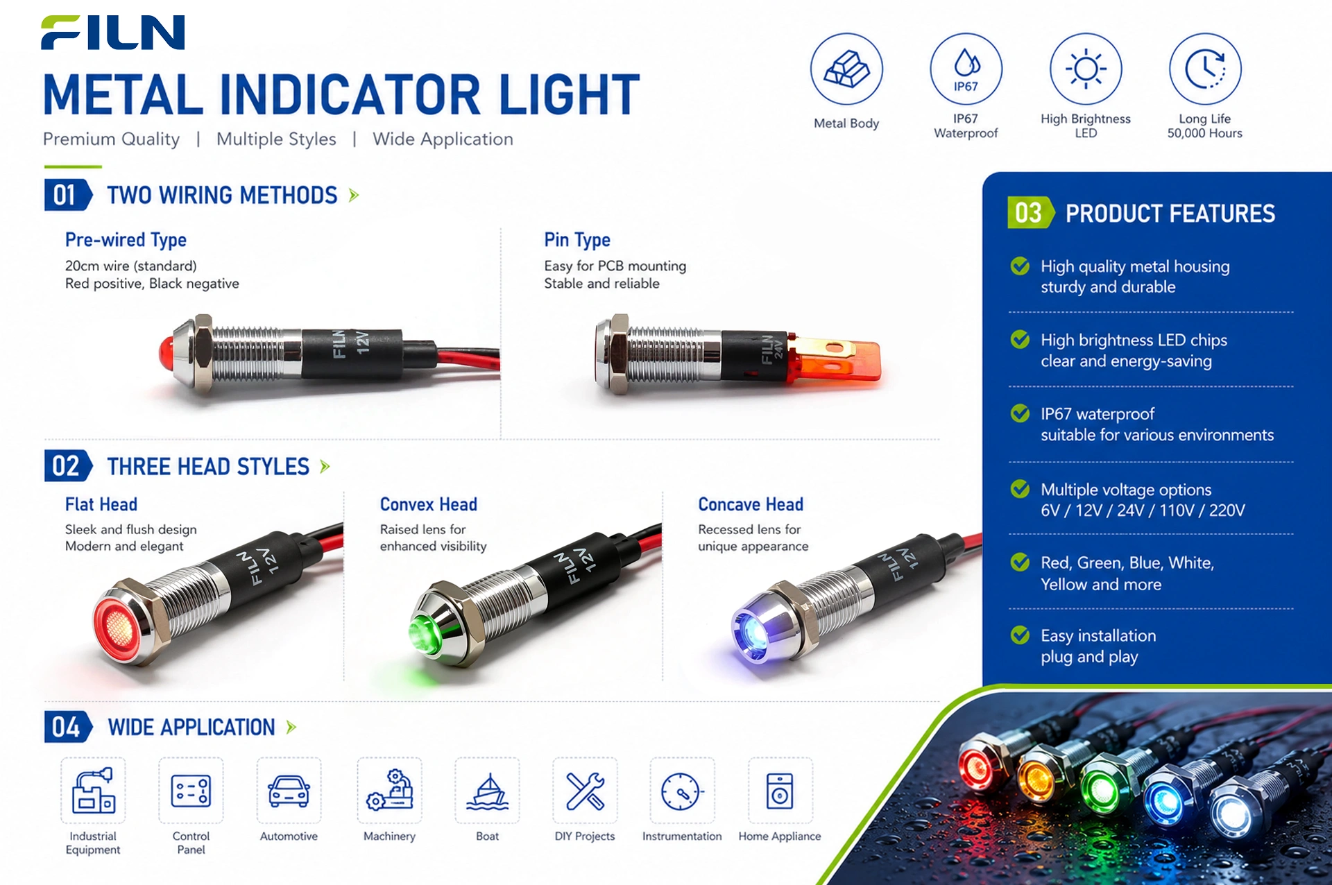
FILN offers two primary categories of indicator lights: metal indicator lights and plastic indicator lights. Available mounting sizes range comprehensively from 6mm to 30mm. Regarding electrical connection methods, buyers can select between pin terminal configurations or direct wire lead options. Furthermore, metal indicator lights feature three distinct exterior head styles—flat head, prominent (convex) head, and recessed head—allowing engineers to select configurations tailored precisely to operational visibility and panel design needs.
Product Overview
The FILN metal indicator light is engineered as a heavy-duty pilot device designed to withstand rigorous industrial operating environments. It operates by converting electrical energy into visible optical signals, providing real-time status indication for complex electrical systems and automated machinery. Mechanically, the unit features a precision-machined threaded housing secured by a stainless steel lock washer and a silicone O-ring, ensuring stable physical retention on control panels up to specific thickness limits.
The electrical architecture integrates a carbon film or specialized voltage-dropping resistor matched with a high-efficiency solid-state LED chip, regulating forward current to prevent thermal runaway. Main applications include industrial control panels, power distribution boards, transportation dashboards, and renewable energy storage systems. Industrial advantages include vibration resistance, extended operational lifespan exceeding 50,000 hours, and robust protection against moisture and dust ingress. FILN manufacturing adheres to strict quality benchmarks, with applicable models supporting global compliance requirements.
Quick Specifications
| Technical Parameter | Specification Details |
|---|---|
| Product Description | Metal indicator light with wires / pin terminals |
| Indicator Light Model | FILN Industrial Series (Configuration Dependent) |
| Mounting Hole Size | 6mm to 30mm (0.24 in to 1.18 in) |
| Voltage Rating | 3V–480V AC/DC (Customizable) |
| LED Color Options | Red, Green, Yellow, Blue, White, Bi-color, Tri-color |
| Waterproof Rating | IP65 / IP67 Ingress Protection |
| Wiring Type | Pin terminal or integrated wire lead |
| Head Type | Flat head, prominent head, recessed head |
| Surface Quality | Smooth and flat without burrs, oxidation, cracks, or visible defects. |
| Assembly Requirements | Head and base assemblies properly fitted; zero rotation, detachment, tilt, or deformation. |
Performance Parameters
| Performance Metric | Rated Value / Standard |
|---|---|
| Rated Operating Voltage | 3V–480V DC/AC (Customized per customer requirements) |
| AC Frequency | 50/60 Hz |
| Rated Operating Current | ≤ 20 mA |
| Rated Power | Approx. 0.2 W |
| Insulation Resistance | ≥ 100 MΩ (Tested at 500V DC between lead wires and housing) |
| Dielectric Strength / Voltage Proof | 1500V–1800V AC, no breakdown or flashover |
| Operating Life | 50,000 to 100,000 hours (50,000 h – 100,000 h) |
| Ingress Protection Rating | IP65 / IP67 |
Component Materials & Engineering Purpose
| Component Part | Material Specification | Engineering Purpose & Function |
|---|---|---|
| Shell | Copper alloy / Black-plated zinc-aluminum alloy | Provides mechanical impact resistance, grounding, and corrosion protection. |
| Lamp Holder | PA66 (Polyamide 66) | Ensures thermal stability and high dielectric insulation around internal circuitry. |
| Lampshade / Lens | PC (Polycarbonate) | Delivers high optical clarity, light diffusion, and shatterproof impact strength. |
| Luminescent Source | High-brightness LED | Generates efficient optical status signaling with low power consumption. |
| Resistor | Carbon film resistor | Regulates operating current and drops voltage safely across the circuit. |
| Wire / Lead Wire | PVC | Insulates electrical conductors with flexible, flame-retardant outer sheathing. |
| Nut | Copper alloy | Secures the indicator firmly against control panel plates without thread stripping. |
| O-Ring | Silicone / Silica gel | Seals panel joints against water, oil, and dust ingress (IP67 compliance). |
| Lock Washer / Gasket | Stainless steel | Prevents fastener loosening under continuous industrial vibration. |
Environmental Performance
Application scope: This specification establishes the general operating parameters for the FILN metal indicator light series.
| Environmental Test Parameter | Test Condition & Specification Limit |
|---|---|
| Part Name | Metal indicator light |
| Operating & Storage Temperature | -40℃ ~ +80℃ |
| Operating Relative Humidity | ≤85% at +40℃ |
| High Temperature Test | 96 hours at 80±2℃ |
| Low Temperature Test | 96 hours at -40±2℃ |
| Constant Temperature & Humidity Test | 96 hours at 40±2℃, 90%~95%RH |
| Temperature Cycling Test | Alternate between -40℃ (30 min) and 85℃ (30 min), 5 cycles total |
LED Technical Specifications
Absolute Maximum Ratings
Maximum safe operating limits of the integrated LED chip:
| Parameter | Rating Limit |
|---|---|
| Maximum Forward Current (IFP) | 20 mA |
| Reverse Voltage (VR) | 5 V |
| Power Dissipation (PD) | 60 mW |
| Operating Temperature (TOPR) | -40°C ~ +80°C |
| Storage Temperature (TSTG) | -40°C ~ +100°C |
| Lead-Free Soldering Temperature (TSOL) | Max. 260°C for 3 sec. Max. |
Electro-Optical Characteristics
Test parameters measured at an ambient temperature of Ta = 25°C:
| Parameter | Test Condition | Parameter Range / Limit |
|---|---|---|
| Forward Voltage (VF) | IF = 20 mA | 2.8 V (Min.) ~ 3.2 V (Max.) |
| Reverse Current (IR) | VR = 5 V | 5 µA (Max.) |
| Viewing Angle (2θ₁/₂) | IF = 20 mA | 60° (Typical) |
| Luminous Intensity (Iv) | IF = 20 mA | 500 mcd (Min.) ~ 800 mcd (Max.) |
| Recommended Forward Current (IF) | - | 20 mA (Typical) |
| Dominant Wavelength (λd) | IF = 20 mA | 520 nm ~ 525 nm |
| Junction Temperature (Tj) | IF = 20 mA | 125°C (Max.) |
| Thermal Resistance (RJP) | IF = 20 mA | 8°C/W (Typical) |
Standard Test Conditions
Unless otherwise specified, all electrical and optical parameters are measured under the following standard atmospheric conditions:
- Ambient Temperature: 5℃ ~ 35℃
- Relative Humidity: 45% ~ 85%
- Air Pressure: 86 ~ 106 kPa (860 ~ 1060 mbar)
Notes: Luminous intensity and dominant wavelength are calibrated in accordance with the CIE international standard of human eye response curve. Tolerance of luminous intensity measurement is ±15%, and voltage measurement tolerance is ±0.1V.
Applications by Industry
Metal indicator lights utilize high-strength copper alloy or stainless steel metal shells, delivering exceptional impact resistance and an IP67 waterproof and dustproof rating, making them ideal for industrial and high-end commercial applications. While plastic indicator lights are prone to aging, fragmentation, and high-temperature deformation over time, metal indicator lights adapt seamlessly to harsh working conditions, frequent operation, and high-reliability environments.
1. Industrial Automation & Machinery Manufacturing
This sector represents the largest and most core application field for metal indicator lights, characterized by continuous mechanical vibration, oil contamination, and hard object impacts.
- CNC Machine Tools & Machining Centers: Control panels feature red, green, and yellow metal indicator lights where green denotes normal operation, yellow signifies standby/warning, and red indicates emergency stop or system fault. Metal shells resist cutting fluid and metal chip corrosion.
- Automation Production Line Control Cabinets: Large distribution cabinets and PLC control enclosures use 6mm and 8mm metal indicators compatible with AC220V and DC24V to display power circuit status.
- Hydraulic & Pneumatic Equipment: Applied for oil pump start/stop and over-pressure alerts. Integrated wire-lead metal indicators prevent lead breakage and loosening caused by severe equipment vibration compared to pin-terminal variants.
2. Outdoor Power & New Energy Distribution Systems
Outdoor equipment subjected to year-round solar radiation, precipitation, and extreme thermal fluctuations requires stringent high/low temperature tolerance and weather resistance.
- New Energy Charging Piles: DC and AC outdoor charging stations feature flat-head metal status indicators where flashing blue/green indicates active charging, steady light denotes full charge, and flashing red warns of ground faults. IP67 waterproof and vandal-resistant construction supports high-frequency public usage.
- Outdoor Distribution Boxes & Photovoltaic Combiner Boxes: Solar photovoltaic stations and municipal outdoor distribution boxes utilize indicators to display high-voltage closing and inverter running status across a -40℃ to 80℃ operating range.
3. Rail Transit, Engineering Vehicles & Marine Equipment
Vehicles and marine vessels experience intense shock, mechanical vibration, and high salt-fog atmospheric corrosion.
- Engineering Vehicle Dashboards: Excavators, cranes, and bulldozer operator cabins employ panel lights for oil pressure, water temperature, lighting, and braking fault warnings under severe dust and shock conditions.
- Marine & Port Control Equipment: Ship bridge panels and deck control boxes use electroplated stainless steel metal indicators to resist saltwater corrosion, supported by silicone sealing rings to block moisture ingress.
4. Commercial Self-Service & Public Security Facilities
Public equipment is highly susceptible to physical impact and vandalism, making plastic fixtures unsuitable.
- Vending & Ticketing Machines: Paired with vandal-resistant metal pushbuttons to indicate coin insertion, dispensing, and change status.
- Fuel Dispenser Panels: Hazardous fuel zones require strict electrical isolation, which metal indicator housings provide to enhance operational safety.
- Outdoor Access Control & Video Intercoms: Stainless steel access panels incorporate red and green indicators to denote door lock status.
5. Medical Equipment & Food Processing Machinery
Industries requiring frequent high-pressure washdown and chemical sterilization demand high cleanliness standards.
- Food Filling & Packaging Equipment: Daily high-pressure hot water and chemical washdowns are resisted by IP67 metal indicators, preventing internal component corrosion.
- Medical Sterilization Equipment: High-temperature autoclaves use indicator lights to differentiate heating, sterilization, and exhaust phases.
Summary: Standard plastic indicators degrade, yellow, and embrittle under UV exposure, while workshop oils corrode housings and continuous vibration causes pin loosening. Metal indicator lights with copper alloy bodies, silicone waterproof O-rings, and tail-integrated wiring structures resolve these challenges, making them the preferred component for reliable industrial equipment operation.
LED Indicator Color Meanings and Application Guide
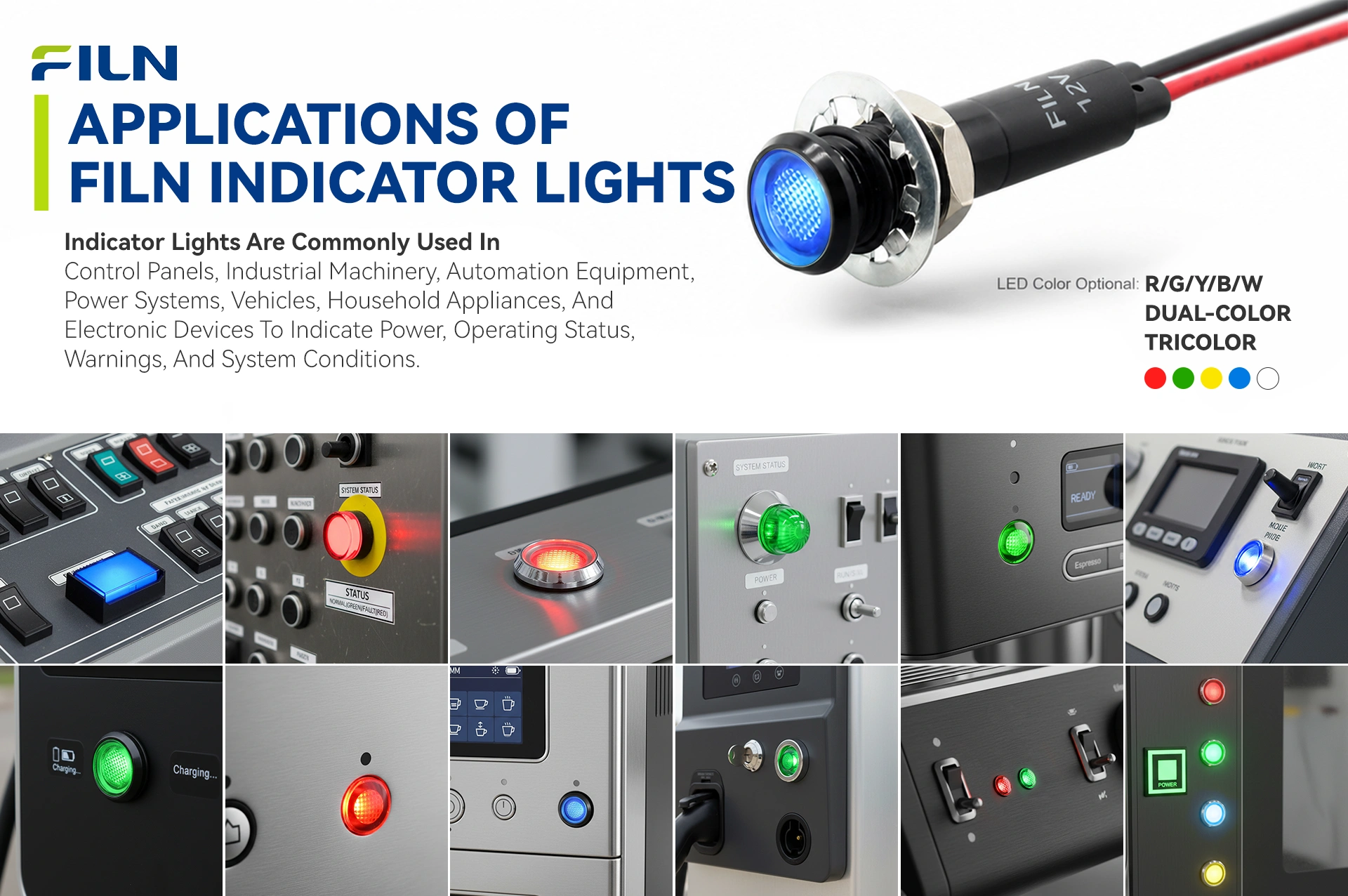
Indicator light colors convey critical operational states across industrial control panels. The five standard colors—Red, Green, Yellow/Amber, Blue, and White—each serve specific functional roles in human-machine interfaces.
- Red: Denotes danger, emergency stop, fault, or critical alarm status. Typically wired to emergency stop loops or thermal overload relays.
- Green: Signifies normal operation, safe conditions, power-on status, or cycle completion. Widely used on main power supply rails and running machinery.
- Yellow / Amber: Indicates caution, abnormal operating conditions, pre-warning states, or standby modes requiring operator attention.
- Blue: Used for mandatory action, specific operational modes, or informational status such as cooling system active or EV charging state.
- White: Represents general illumination, neutral system status, or normal power availability without safety implications.
Note that indicator color conventions can vary by equipment manufacturer, control-system design, industry standard, country, and application. FILN offers single-color, dual-color, and tri-color indicator configurations where applicable.
| Color | Common Meaning | Typical Status | Typical Application | Recommended Environment |
|---|---|---|---|---|
| Red | Danger / Alarm | Fault / Emergency | E-Stop / Motor Overload | All industrial control panels |
| Green | Normal / Safe | Running / Active | Power ON / Cycle Start | Machine tool consoles |
| Yellow | Caution / Warning | Standby / Pre-alarm | Temperature alert / Oil check | Automation monitoring racks |
| Blue | Mandatory Action | Charging / Cooling | EV Charger / Auxiliary mode | Outdoor equipment / EV stations |
| White | Neutral / General | Normal Power Available | Control cabinet illumination | Indoor distribution boards |
Installation Guide
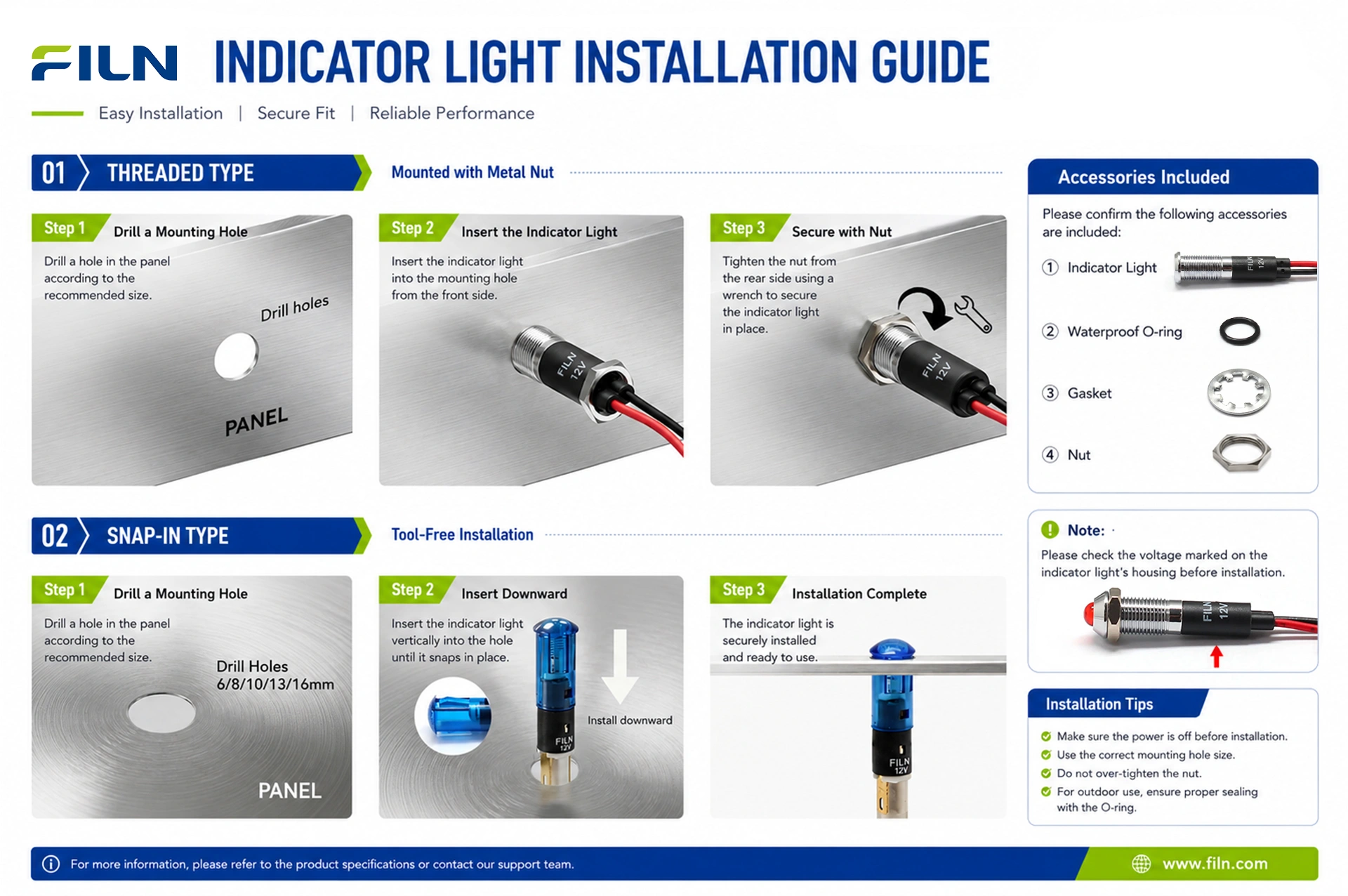
Proper mechanical and electrical installation ensures the longevity and IP67 waterproof integrity of FILN metal indicator lights. Follow this structured installation procedure:
- Safety Preparation: Disconnect all power sources and verify zero energy state using calibrated testing equipment before handling wiring.
- Tool Gathering: Prepare a calibrated hole punch or drill, wire strippers, crimping tools, insulating tape or heat-shrink tubing, and a torque wrench if required.
- Mounting Preparation: Measure the exact diameter of the indicator model (e.g., 8mm, 12mm, 22mm) and mark the panel drilling location precisely.
- Panel Machining: Drill the mounting hole into the control panel, ensuring the surface is clean, deburred, and free of metal shavings that could damage insulation.
- O-Ring Placement: Ensure the silicone waterproof O-ring is correctly seated on the indicator body threads directly beneath the indicator head flange.
- Panel Insertion: Insert the indicator body through the front of the control panel mounting hole.
- Fastening: Thread the copper alloy mounting nut and stainless steel lock washer from the rear of the panel. Tighten securely to compress the O-ring, avoiding over-torquing which may strip threads.
- Wiring Connection: Connect the power leads or pin terminals according to the electrical schematic, maintaining correct polarity for DC models.
- Insulation & Protection: Secure wire connections using quick-link terminals, soldering, or professional electrical wrapping to prevent short circuits.
- Post-Installation Inspection: Inspect panel alignment, verify secure mechanical fixing, and test electrical operation prior to full system commissioning.
Wiring Guide
FILN indicator lights are manufactured in two primary electrical connection formats: pin-terminal models and wire-lead models. Understanding proper connection techniques ensures connection stability and operational safety.
Pin-Terminal Indicators: These models feature solder lugs or blade terminals. Connections can be made using insulated quick-disconnect receptacles (push-on terminals) or by directly soldering wires to the pins using appropriate heat-shrink tubing for insulation and strain relief.
Wire-Lead Indicators: Direct wire-lead indicators come equipped with factory-attached PVC cables. These can be connected to main control circuits using professional quick-link wire connectors, terminal blocks, solder splicing, or electrical tape wrapping to guarantee connection stability and prevent accidental loosening from vibration.
Safety Notice: Always ensure electrical safety compliance by disconnecting and cutting off power before performing any wiring or installation work.
Industry Knowledge Center
Industrial pilot devices operate as the visual interface between complex electronic logic and human operators. Understanding their underlying electrical principles helps engineers select appropriate components, prevent premature failures, and maintain system compliance across harsh industrial settings.
Selection considerations should always prioritize operating voltage compatibility (AC versus DC), environmental protection requirements (IP65/IP67), and physical panel cutout dimensions. Common maintenance procedures involve periodically checking terminal tightness and inspecting sealing gaskets in high-vibration or washdown environments.
Buyer Decision Guide & RFQ Checklist
Selecting the correct metal indicator light requires evaluating physical, electrical, and environmental specifications against operational demands.
Material Selection Comparison
| Shell Material | Advantages | Limitations | Best Environment |
|---|---|---|---|
| Brass Nickelled (Copper Alloy) | High mechanical strength, excellent electrical conductivity, cost-effective. | May corrode in continuous marine salt-spray without specialized plating. | General industrial machinery, indoor control panels. |
| Stainless Steel | Superior corrosion resistance, aesthetic finish, extreme durability. | Higher material cost relative to brass or zinc alloy. | Food processing, marine, medical, outdoor public installations. |
| Zinc-Aluminum Alloy (Black-Plated) | Lightweight, robust die-casting capability, premium matte black appearance. | Lower impact tolerance compared to solid stainless steel or brass. | Automotive dashboards, commercial electronic appliances. |
Specification-to-Decision Framework
- Mounting Hole: Determines physical compatibility with existing panel punchouts (e.g., 8mm, 12mm, 16mm, 22mm).
- Voltage & Circuit Type: Determines electrical compatibility (AC/DC 12V, 24V, 110V, 220V, etc.). Choosing incorrect voltage causes dim illumination or component burnout.
- IP Rating: Determines environmental suitability. Select IP67 for washdown or outdoor exposure.
RFQ Checklist for Buyers
Providing these specifications helps FILN engineering and sales teams confirm product compatibility and quotation requirements efficiently:
- Product type and model series
- Mounting hole size (mm)
- Operating voltage and AC/DC type
- LED illumination color
- Head type (flat, prominent, recessed)
- Shell material preference
- Waterproof requirement (IP65 / IP67)
- Wiring method (pin terminal vs. wire lead) and wire length
- Certification requirements (UL, CE, RoHS, etc.)
- Quantity, packaging, OEM / logo marking requirements, and target destination market
FILN Manufacturing and Engineering Capabilities
Yueqing Yulin Electronic Co., Ltd. (operating under the FILN brand) provides verified manufacturing, R&D, and custom engineering support for global industrial clients. FILN maintains dedicated engineering teams specializing in OEM and ODM customization, supporting small-batch prototyping as well as large-scale mass production. Rigorous internal quality control protocols, integrated mold design capabilities, and fully equipped electrical testing laboratories ensure that every production batch meets strict international compliance and performance benchmarks.

Factory Direct Supply & Company Profile
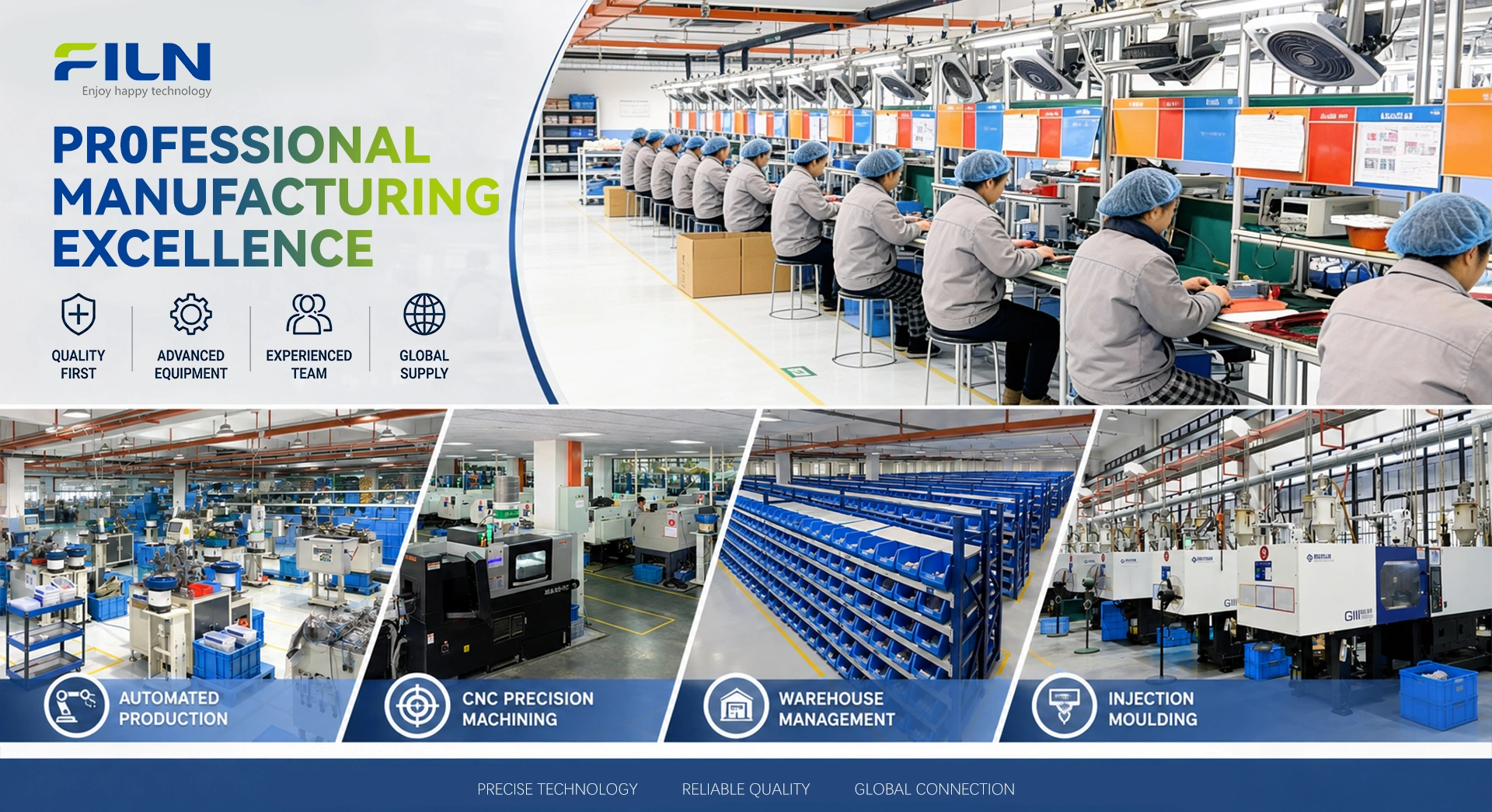
Yueqing Yulin Electronic Co., Ltd., brand name FILN, located in Wenzhou, Zhejiang, was established in 2006 as a professional electrical switch manufacturer integrating R&D, production, and sales. Its premium FILN brand products are sold in over 100 countries. FILN operates a modern 10,000 m² facility with 20+ advanced production lines and an independent testing lab. Driven by scientific processes and the ISO9001 quality system, FILN ensures industry-leading innovation and electrical performance. Certified products (UL, CE, RoHS, REACH, TUV, CB) are widely used in kitchen appliances, energy storage, EV charging, automotive, marine, and security systems.
- Production Capabilities: Indicator lights, pushbutton switches, rocker switches, toggle switches, and other small electrical appliances, alongside fully customized production services.
- Quality System & Certifications: ISO9001, CE, VDE, RoHS, SGS, UL, IP65, TUV.
- Export Markets: Global distribution across North America, Europe, Asia, and Oceania.
- Manufacturing Advantages: Professional engineers on hand, specialized in customized solution development to resolve complex technical challenges.
- Official Website: www.filn.com
- Direct Inquiry Email: inquiry@cnylin.com.cn
Frequently Asked Questions
How to prevent phantom illumination (faint glowing) in 12V LED indicators?
Phantom illumination or faint glowing in 12V LED indicator lights is typically caused by leakage current from solid-state PLC outputs, triacs, or long cable capacitance. To resolve this, installing a parallel resistor (bleeder resistor) across the indicator terminals will shunt stray leakage current away from the LED diode, eliminating the unwanted micro-glow state while maintaining normal powered illumination.
Can this IP67 indicator light be washed down with caustic chemicals?
Yes, models manufactured with stainless steel shells and food-grade silicone O-rings are engineered to withstand regular high-pressure washdowns and industrial caustic cleaning agents. However, standard brass nickelled models should be evaluated for chemical compatibility if exposed continuously to aggressive solvents.
What is the difference between pin-terminal and wire-lead indicator lights?
Pin-terminal indicators feature exposed metal pins requiring push-on receptacles or direct soldering during assembly, making them ideal for modular panel wiring. Wire-lead indicators come equipped with factory-attached insulated cables, saving installation time and providing enhanced moisture protection right out of the box.
Do FILN metal indicator lights require external resistors for high voltages?
No. FILN indicator lights designed for voltages above 12V/24V (such as 110V, 220V, or 380V AC/DC) feature internal current-limiting carbon film resistors integrated directly into the housing assembly, allowing safe direct connection to rated power supplies.
What mounting hole diameters are available for FILN metal indicators?
FILN manufactures metal indicator lights in a comprehensive range of standardized mounting hole diameters, including 6mm, 8mm, 10mm, 12mm, 14mm, 16mm, 19mm, 22mm, 25mm, and 30mm, accommodating virtually any industrial panel design.
Are AC and DC voltages interchangeable on standard LED indicator lights?
It depends on the internal circuit configuration. While some models are specifically manufactured with internal bridge rectifiers supporting both AC and DC operation, others are polarity-sensitive or restricted to specific current types. Always verify the part number specification before applying power.
How does an IP67 rating protect the indicator in outdoor environments?
An IP67 rating indicates that the housing is completely dust-tight and capable of withstanding water immersion up to 1 meter depth for 30 minutes. Combined with the silicone O-ring, it prevents moisture and rain ingress on outdoor machinery and EV charging stations.
Can FILN customize wire lengths and connector types for bulk orders?
Yes. As a direct manufacturer, FILN offers extensive OEM and ODM customization services, including custom wire lengths, specialized terminal connectors (such as XH, PH, or waterproof plugs), and custom laser-etched symbols.
What is the typical operational lifespan of a FILN LED indicator light?
Under rated voltage, operating current, and standard environmental conditions, FILN LED indicator lights provide a long operational lifespan ranging from 50,000 to 100,000 hours of continuous illumination.
How can I request product samples for testing and evaluation?
You can request samples directly by contacting FILN engineering and sales via email at inquiry@cnylin.com.cn or visiting www.filn.com to discuss specific technical requirements and sample availability.
Dear Valued Customers,
At FILN, we specialize in delivering precision-engineered indicator lights, push button switches, and rocker switches tailored to your unique requirements. While our products default to standard voltage ranges (12-24V and 110-220V), we understand that specialized applications demand flexibility.
Need a Custom Voltage Solution? Simply inform us of your desired voltage specifications (e.g., 5V, 48V, or non-standard ranges), and our engineering team will craft a solution within 10-15 business days.
Why Choose FILN for Custom Manufacturing?
✅ Expertise You Can Trust: Over 20 years of experience in industrial-grade electronic component production.
✅ End-to-End Customization: From voltage adjustments to bespoke designs (shape, color, IP rating), we adapt to your needs.
✅ Quality Guaranteed: All custom orders undergo rigorous testing to meet CE/RoHS/IP65 standards.
✅ Scalable Support: Whether prototyping or bulk orders, we ensure seamless delivery.
How It Works
Consultation: Share your technical requirements via email or our contact form.
Design & Approval: Receive 3D models or samples for confirmation.
Production & QC: Precision manufacturing with real-time updates.
Global Shipping: Trackable logistics to your doorstep.
Contact Us Today
Email: inquiry@cnylin.com.cn
- Choosing a selection results in a full page refresh.