


Rocker Switch Technical Drawing

What is a 2 Position Rocker Switch?
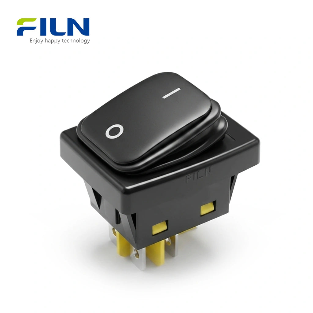
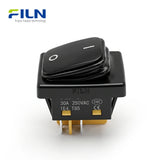
A 2 position rocker switch is a mechanical switch used to control the flow of electricity in a circuit, typically featuring "ON" and "OFF" states. As a core component in the KCD4 series, this switch utilizes a rocking motion to bridge or disconnect internal contacts. The FILN FL3-KCD4-0322-21 is a high-performance, non-illuminated model designed for durability in industrial and commercial environments, offering a sleek black aesthetic that fits universally into any panel design.
Product Overview
The FILN 2 position rocker switch is engineered for heavy-duty applications, supporting up to 30A 250VAC. This KCD4 rocker switch features a 30x22mm cutout and a robust IP65 waterproof rating, making it ideal for outdoor machinery, commercial kitchen equipment, and power tools. With certifications including UL, CE, VDE, RoHS, and ISO9001, it ensures global compliance and safety. The 4-pin DPST configuration allows for simultaneous control of two lines, providing a complete circuit break for enhanced safety. Its snap-in design facilitates rapid installation on panels, while the reinforced internal frame provides structural integrity against mechanical stress.
Quick Specifications
| Model Number | FL3-KCD4-0322-21 |
|---|---|
| Mounting Size | 30 x 22 mm (1.18 x 0.87 inch) |
| Switch Function | ON-OFF (2 Position) |
| LED Color | Non-Illuminated (Black Surface) |
| Head Shape | Rectangular |
| Wiring Method | 4-Pin Quick Connect Terminals (Spade) |
Performance Parameters
| Main Technology Performance | |
|---|---|
| Rated Voltage/Current | 30A 250VAC / 18(12)A 125VAC |
| Initial Contact Resistance | ≤50mΩ |
| Insulation Resistance | ≥100mΩ / 500VDC |
| Dielectric Strength | 1500VAC / 5mA 60s |
| Ambient Temperature | -40°C to +125°C |
| Protection Degree | IP65 / IP66 Waterproof |
| Certifications | ISO9001, CE, VDE, RoHS, UL |

Component Materials
| Accessories Name | Material |
|---|---|
| Transparent Sheet / Guiding Part | Premium PC |
| Holder / Up & Middle Base | ABS (High Impact) |
| Bottom Base | PA66 (Heat Resistant) |
| Pin / Spring Board | Brass H62 |
| Contact Points | Silver Alloy AgCdO12 |
| Case | 08F Iron Case (Corrosion Proof) |
| Waterproof Cover | High-Quality Rubber |
Technical Advantages: 30A High-Current Series
The FILN 30A High-Current Rocker Switch is engineered for extreme power loads. Below is the technical upgrade breakdown:
| Core Component | Upgrade Description | Performance Benefit |
|---|---|---|
| Housing Structure | Split Black Housing Design | Superior structural stability and enhanced sealing. |
| Waterproof Design | Optimized Frame Surface | Significant improvement in IP ratings and panel fit. |
| Contact Material | Silver Contacts + 1mm Brass | True 30A rating with high electrical endurance. |
| Inner Holder | Larger Contact Holder | Reduces heat generation during heavy-duty operation. |
Application & Selection Guide
For heavy-duty applications such as Industrial Control Panels, Portable Power Stations, and Marine Systems, the 30A Upgraded Model is highly recommended for maximum safety.

The Difference Between Framed and Frameless Design
FILN's professional KCD4 series offers two distinct structural designs to meet different installation requirements:
1. Reinforced Framed Version (Enhanced Series): Features an internal white frame that acts as an "exoskeleton." This design prevents the switch body from cracking and ensures the waterproof cover remains anchored in high-vibration marine environments.
2. Classic Standard Version (Frameless): A compact design ideal for limited panel space. Shares the same high-quality silver contacts, offering a cost-effective solution for dry, stable environments.

Industrial and Commercial Applications
- Home Appliances: Coffee makers, air fryers.
- Industrial Control: Distribution boxes, machinery.
- Marine/RV: Dashboards and lighting controls.
- Office Gear: PDU power strips, printers.

Installation & 4-Pin Wiring Logic
- Create a rectangular 30x22mm cutout on the panel.
- Connect power wires to the bottom pins (Input) and load wires to the top pins (Output).
- Snap the switch into the hole; side clips will lock it automatically.
Note: The 4-pin non-illuminated version acts as a DPST (Double Pole Single Throw), disconnecting both Live and Neutral simultaneously for maximum electrical safety.

Complete Rocker Switch Wiring Diagram and Connection Guide
A 4 pin rocker switch wiring diagram is essential for managing higher-current loads or providing clear visual feedback in electrical systems. These switches are typically Double Pole Single Throw (DPST) or specialized single-pole configurations that allow the internal lamp to function independently or in synchronization with the connected device. Depending on your requirements, rocker switch wiring can be configured for either "Independent Illumination" (Always On) or "Dependent Illumination" (On when Device is Active).
Option 1: Light On When Device is Operating (Dependent Illumination)
This configuration is ideal when you need a visual status indicator to show that the equipment is currently powered. In this mode, the internal LED only illuminates when the switch is toggled to the "Press" position.
- Input Connection: Connect the positive (+) and negative (-) wires from the power source to the bottom set of pins.
- Output Connection: Connect the positive and negative terminals of your device to the top set of pins.
- Logic: When the switch is closed, current flows through the device and simultaneously completes the internal circuit for the LED lamp.

Figure 1: Wiring for LED illumination during device operation.
Option 2: Switch Light Remains Constantly Lit (Independent Illumination)
This setup is useful for locating the switch in dark environments (such as vehicle dashboards or industrial control panels). The internal LED remains on as long as the power source is connected, regardless of the device status.
- Input Connection: Connect the power source positive (+) and negative (-) wires to the top set of pins (where the internal lamp is internally bridged).
- Output Connection: Connect the device terminals to the bottom set of pins.
- Logic: The LED is powered directly by the input line, while the rocker mechanism acts as a gatekeeper only for the current flowing to the device.

Figure 2: Wiring for constant LED illumination (Switch Finder Mode).
Comparison of Operation Logic
| Configuration Type | Switch State | Device Status | LED Status |
|---|---|---|---|
| Dependent (Option 1) | Normal | OFF | OFF |
| Press | ON | ON | |
| Independent (Option 2) | Normal | OFF | ON |
| Press | ON | ON |
Technical Considerations & Safety Notes
- Pin Orientation: 4-pin rocker switches usually have two parallel circuits. Ensure you are wiring the positive and negative on the correct pairs to avoid a short circuit.
- Voltage Matching: Check if the internal lamp is designed for 12V DC or 110V/220V AC. Using an AC lamp on a DC circuit will result in no light, while the reverse may cause the lamp to explode.
- Amperage Ratings: Most 4-pin industrial switches (like the KCD4 series) support up to 15A-30A. Verify that your total load does not exceed the manufacturer's specification.
- Termination: Use high-quality 6.3mm female spade connectors. Ensure they are fully insulated to prevent accidental contact between adjacent terminals.
FILN Factory Direct Supply
Leading global manufacturer offering professional customization and rapid delivery.
No MOQ
Fast Global Shipping
Custom Wire Assembly
Free Engineering Samples
Request Free Samples

Frequently Asked Questions
1. What is the cutout size for a KCD4 rocker switch?
The standard industry cutout size is 30x22mm, fitting panels with a thickness of 1mm to 3mm.
2. Is this switch waterproof for outdoor use?
Yes, this model features an IP65 rating when used with the provided rubber gasket and frame.
3. Can I use a 4-pin rocker switch for a 2-pin application?
Yes, you can simply use one side (two pins) of the switch to control a single line.
4. What is the benefit of a non-illuminated black rocker switch?
Black non-illuminated switches are universal, aesthetically versatile, and do not require a neutral wire for an internal lamp.
5. Can it handle 30 Amps safely?
Yes, FILN's FL3-KCD4 is rated specifically for heavy-duty 30A 250VAC applications.
6. Does it come with wires?
The standard version has 6.3mm spade pins, but FILN offers customization for pre-soldered wires and connectors.
7. What does the internal frame do?
The internal frame provides structural rigidity, ensuring the switch housing doesn't deform during high-force installation.
8. Is the switch DPST or SPST?
The 4-pin version is a DPST (Double Pole Single Throw), allowing it to cut both live and neutral lines.
9. Are these switches UL certified?
Yes, all FILN industrial rocker switches carry UL, CE, and RoHS certifications for global export.
10. How do I install it on a metal panel?
Simply snap the switch into the 30x22mm hole; the side plastic tabs will lock it into place automatically.
Dear Valued Customers,
At FILN, we specialize in delivering precision-engineered indicator lights, push button switches, and rocker switches tailored to your unique requirements. While our products default to standard voltage ranges (12-24V and 110-220V), we understand that specialized applications demand flexibility.
Need a Custom Voltage Solution? Simply inform us of your desired voltage specifications (e.g., 5V, 48V, or non-standard ranges), and our engineering team will craft a solution within 10-15 business days.
Why Choose FILN for Custom Manufacturing?
✅ Expertise You Can Trust: Over 20 years of experience in industrial-grade electronic component production.
✅ End-to-End Customization: From voltage adjustments to bespoke designs (shape, color, IP rating), we adapt to your needs.
✅ Quality Guaranteed: All custom orders undergo rigorous testing to meet CE/RoHS/IP65 standards.
✅ Scalable Support: Whether prototyping or bulk orders, we ensure seamless delivery.
How It Works
Consultation: Share your technical requirements via email or our contact form.
Design & Approval: Receive 3D models or samples for confirmation.
Production & QC: Precision manufacturing with real-time updates.
Global Shipping: Trackable logistics to your doorstep.
Contact Us Today
Email: inquiry@cnylin.com.cn
- Choosing a selection results in a full page refresh.