

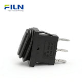


Rocker Switch Drawing

What is a 3 Position Rocker Switch?
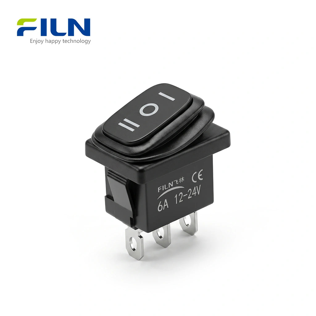
A 3 position rocker switch is a specialized electrical component designed to control two independent circuits through a single physical interface. Operating on a Single Pole Double Throw (SPDT) principle, this switch features three distinct states: ON-OFF-ON. In the central position, the circuit remains open (OFF), while the two outer positions close separate paths to direct power to different loads. The 13x19.5mm form factor is the industrial standard for "Mini" rocker switches, providing a compact yet robust solution for power management in diverse electronic environments.
Product Overview
The FILN FL3-KCD1-011-13X is a high-performance 3 position rocker switch engineered for precision and durability. This non-illuminated model offers a "all-match" aesthetic, fitting seamlessly into any panel design without the distraction of indicator lights. With ISO9001, CE, VDE, RoHS, SGS, UL, and IP65 certifications, it meets the highest global safety standards. It is widely used in industrial control systems, household appliances, and automotive modifications. As a factory-direct product from FILN, it supports full customization including terminal types and pre-soldered wire leads.
Quick Specifications
| Model Number | FL3-KCD1-011-13X |
|---|---|
| Mounting Size | 13mm x 19.5mm (0.51" x 0.77") |
| Switch Function | ON-OFF-ON (3 Position) |
| LED Illumination | Non-Illuminated (No Light) |
| Actuator Shape | Rectangular / Square Profile |
| Wiring Method | 3-Pin Solder / Quick Connect Terminals |
Electrical Performance Parameters
| Technical Parameter | Standard Value |
|---|---|
| Rated Load | 30A 250VAC / 18(12)A 125VAC |
| Contact Resistance | ≤ 50mΩ (Initial) |
| Insulation Resistance | ≥ 100mΩ / 500VDC |
| Dielectric Strength | 1500VAC / 5mA / 60s |
| Electrical Life | ≥ 10,000 Cycles |
| Protection Degree | IP65 / IP66 |
| Certifications | ISO9001, CE, VDE, RoHS, SGS, UL |

Component Materials
| Part Name | Material |
|---|---|
| Transparent Sheet / Light Guide | Polycarbonate (PC) |
| Holder / Up Base | ABS High-Impact Plastic |
| Waterproof Cover / Washer | Silicone Rubber |
| Bottom Base | PA66 (Flame Retardant) |
| Pins / Spring Board | H62 Brass (Silver Plated) |
| Contact Point | AgCdO12 (Silver Alloy) |
| Spring | 72# Spring Steel |
General Characteristics & Testing Standards
| Item | Technical Requirement |
|---|---|
| Operating Temp | -40℃ to +125℃ (Continuous operation) |
| Mechanical Life | 20,000 Cycles (No load, 60 ops/min) |
| Terminal Strength | Withstands 80N static load for 60 seconds |
| Solderability | 90%+ coverage at 235±5℃ for 3 seconds |
| Resistance to Heat | Maintains function after 72 hours at 125℃ |
Framed vs. Frameless Rocker Switches
FILN offers both "Enhanced Framed" and "Standard Classic" series. The Framed Series features an internal high-strength white frame that acts as an "exoskeleton," preventing deformation during installation in tight panels. It also provides a superior seat for waterproof covers. The Frameless Series is ideal for high-density panel layouts where space is at a premium, offering a sleek, minimalist aesthetic and optimized cost for large-scale production.
Global Applications
- Household Appliances: Coffee machines, air fryers, water dispensers.
- Industrial Control: PDU power strips, distribution boxes, test equipment.
- Medical Equipment: Centrifuges, diagnostic tools, nursing beds.
- Automotive & Marine: RV light control, bilge pumps, dashboard auxiliary switches.

Installation Guide
- Measure and cut a rectangular hole in your panel (13mm x 19.5mm).
- Insert the switch from the front of the panel until the side clips snap into place.
- Ensure the switch is flush and securely held by the clips.
- Connect wires to the 3 rear terminals using female spade connectors or soldering.

Complete 3 Pin 3 Way Rocker Switch Wiring Diagram and Guide
A 3 pin rocker switch wiring diagram is vital for projects requiring control over two separate electrical circuits. This specific configuration, commonly found in KCD1 series switches, operates as a Single Pole Double Throw (SPDT) switch with an "On-Off-On" functionality. It allows a single power source to alternate between two different devices or to remain in a central neutral position where both are disconnected.
How to Wire a 3 Pin 3 Way Rocker Switch: Step-by-Step Instructions
Wiring a 3-way non-illuminated switch involves managing a common power input and two independent output loads. Follow these steps for a correct setup:
- 1. Central Power Input (Common Pin): Connect the positive (+) wire from your power supply to the middle pin of the rocker switch. This pin acts as the common terminal that distributes power to the other two pins.
- 2. Device 1 Connection: Connect the bottom pin of the switch to the positive input of your first device (Device 1). In the "Down" position, the circuit to this device is closed.
- 3. Device 2 Connection: Connect the top pin of the switch to the positive input of your second device (Device 2). In the "Up" position, power is redirected here.
- 4. Grounding the Circuit: Connect the negative (-) terminals of both Device 1 and Device 2 directly back to the negative terminal of the power source. As this is a non-illuminated switch, the switch itself does not require a ground connection.
Switch Operation Logic Table
| Switch State | Device 1 Status | Device 2 Status |
|---|---|---|
| UP Position | OFF | ON (Active) |
| Normal (Middle) | OFF (Resting) | OFF (Resting) |
| DOWN Position | ON (Active) | OFF |
Technical Installation Considerations
- On-Off-On Functionality: This 3-pin configuration is unique because the center position acts as a complete "Off" state for both devices, making it perfect for reversing motors or toggling between two different lighting modes.
- KCD1 Series Ratings: Most KCD1 switches are rated for 6A 250VAC or 10A 125VAC. Ensure your load does not exceed these electrical specifications to prevent internal contact welding.
- Wire Termination: For high-current applications, use high-quality female spade connectors. Ensure they are snugly fitted to the 4.8mm or 6.3mm terminals to maintain low resistance and prevent heat buildup.

Figure 1: 3-Pin 3-Way Rocker Switch Connection Schematic
Industry Knowledge: Rocker vs. Push Button Switches
| Feature | Rocker Switch | Push Button Switch |
|---|---|---|
| Installation | Snap-in (Easy) | Threaded Nut (Slow) |
| Current Load | High (up to 30A) | Moderate (usually <10A) |
| Visual Status | Clear physical angle | Needs LED indicator |
How it works: A rocker switch uses a mechanical "seesaw" mechanism. When one side is pressed, the internal bridge pivots to make contact with a terminal, completing the circuit. In an ON-OFF-ON configuration, the bridge is only in contact with the central terminal in the middle position, preventing any current flow.
FILN Factory Direct Supply
FILN is a leading manufacturer of industrial switches with no MOQ requirements. We offer Fast Global Shipping and extensive Customization options for voltage, wire length, and connectors.
- ✅ No MOQ: Small batch orders welcome.
- ✅ Lead Time: Rapid production and shipping.
- ✅ Certifications: CE, RoHS, UL, ISO9001.
FILN Official Website: www.filn.com
Contact Us: inquiry@cnylin.com.cn

Frequently Asked Questions
Q1: What is the difference between a 3-pin and 2-pin rocker switch?
A: A 2-pin switch is a simple ON-OFF switch for one circuit. A 3-pin 3-position switch allows for ON-OFF-ON control over two different circuits.
A: A 2-pin switch is a simple ON-OFF switch for one circuit. A 3-pin 3-position switch allows for ON-OFF-ON control over two different circuits.
Q2: Why choose a non-illuminated 3-pin switch?
A: Non-illuminated switches are more versatile as they do not have specific voltage requirements for a lamp, making them a "universal fit" for both 12V and 220V systems.
A: Non-illuminated switches are more versatile as they do not have specific voltage requirements for a lamp, making them a "universal fit" for both 12V and 220V systems.
Q3: What are the electrical ratings for the FL3-KCD1?
A: It is rated at 30A 250VAC or 18A 125VAC, making it suitable for high-power industrial loads.
A: It is rated at 30A 250VAC or 18A 125VAC, making it suitable for high-power industrial loads.
Q4: Does FILN provide custom wire harnesses?
A: Yes, we can customize wire length, wire gauge, and pre-install various connectors to save your assembly time.
A: Yes, we can customize wire length, wire gauge, and pre-install various connectors to save your assembly time.
Q5: What certifications does this switch carry?
A: This model is UL, CE, VDE, and RoHS certified, ensuring compliance for export to US and European markets.
A: This model is UL, CE, VDE, and RoHS certified, ensuring compliance for export to US and European markets.
친애하는 고객님께,
FILN에서는 귀하의 고유한 요구 사항에 맞춘 정밀 엔지니어링 지시등, 푸시 버튼 스위치 및 로커 스위치를 제공하는 전문 기업입니다. 저희 제품은 기본적으로 표준 전압 범위(12-24V 및 110-220V)를 따르지만, 특수한 응용 프로그램은 유연성을 요구한다는 것을 이해하고 있습니다.
맞춤 전압 솔루션이 필요하신가요? 원하는 전압 사양(예: 5V, 48V 또는 비표준 범위)을 알려주시면, 저희 엔지니어 팀이 10-15 영업일 이내에 솔루션을 제작해 드립니다.
맞춤 제조를 위해 FILN을 선택해야 하는 이유는?
✅ 신뢰할 수 있는 전문성: 산업용 전자 부품 생산에서 20년 이상의 경험.
✅ 끝에서 끝까지 맞춤화: 전압 조정부터 맞춤형 디자인(형태, 색상, IP 등급)까지, 귀하의 요구에 맞춰 조정합니다.
✅ 품질 보장: 모든 맞춤 주문은 CE/RoHS/IP65 기준을 충족하기 위해 철저한 테스트를 거칩니다.
✅ 확장 가능한 지원: 프로토타입이든 대량 주문이든, 원활한 배송을 보장합니다.
작동 방식
상담: 이메일 또는 연락처 양식을 통해 기술 요구 사항을 공유하세요.
디자인 및 승인: 확인을 위한 3D 모델 또는 샘플을 받습니다.
생산 및 품질 관리: 실시간 업데이트가 포함된 정밀 제조.
글로벌 배송: 귀하의 문앞까지 추적 가능한 물류.
오늘 저희에게 연락하세요
이메일: inquiry@cnylin.com.cn
- Choosing a selection results in a full page refresh.